Great Info About How Do You Tell What Polarity A Device Is

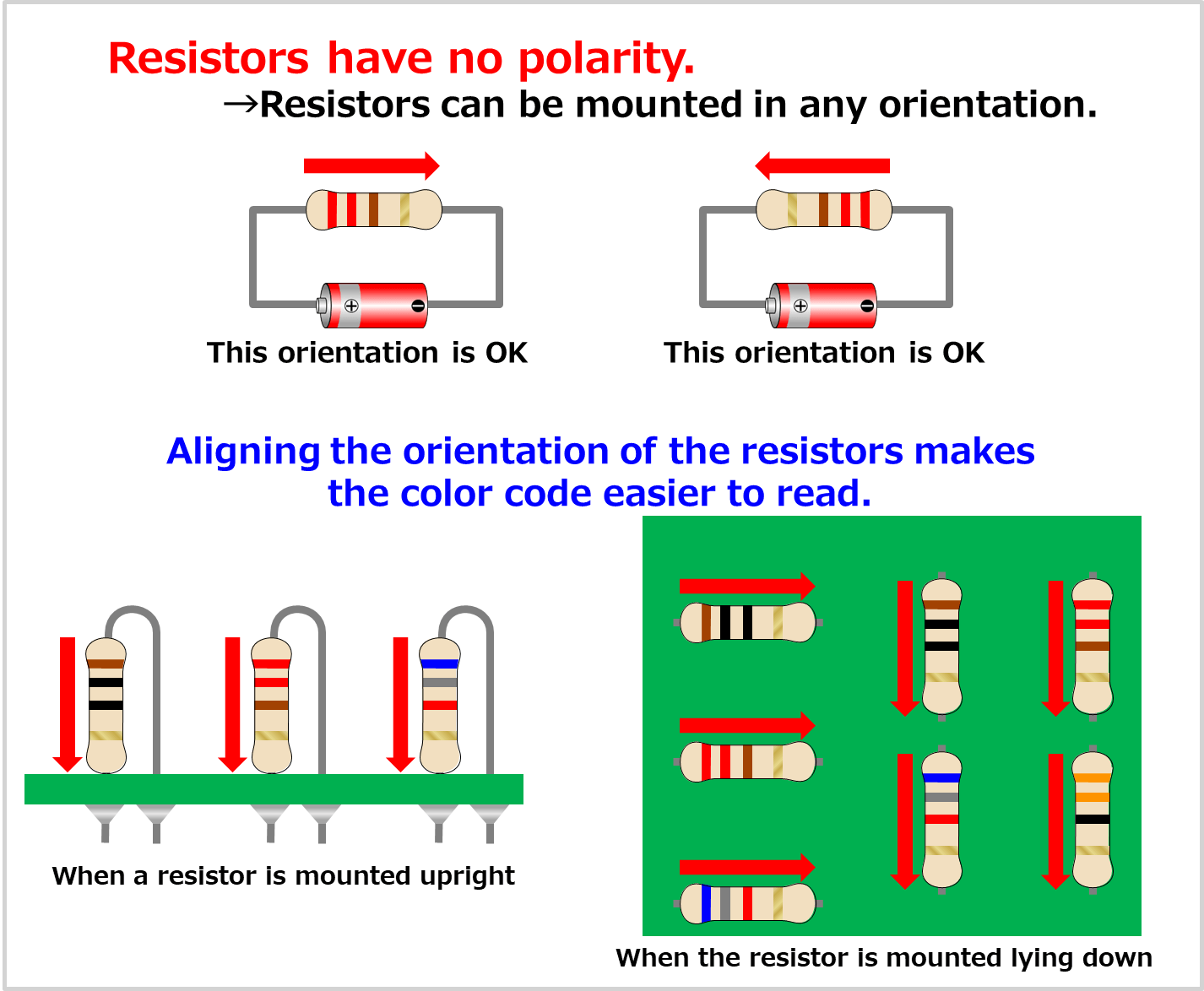
Polarity Of Resistor Electrical Information
Understanding Device Polarity
1. Why Polarity Matters
Ever plugged something in and it just... didn't work? Or worse, shorted out? Chances are, polarity might have been the culprit. Polarity, in the electrical world, is like knowing which way a puzzle piece goes. It refers to whether a circuit component has a positive (+) or negative (-) terminal. Getting it wrong can range from a minor inconvenience to a serious electrical hazard. So, figuring out which end is which is pretty important!
Think of it like this: a battery has a positive and a negative end. Current flows from positive to negative. If you try to force it the other way, things get grumpy. Electronic devices are designed with specific polarity in mind, and reversing it can damage sensitive components. Imagine trying to force a square peg into a round hole — that's what happens when polarity is off. It just doesn't fit, and you might break something in the process.
Many electronic components are polarity-sensitive, meaning they only function correctly when connected in the correct direction. Diodes, LEDs (Light Emitting Diodes), and electrolytic capacitors are common examples. Connecting these components backwards can cause them to fail, sometimes spectacularly! No one wants a miniature explosion in their electronic project, right?
Therefore, correctly identifying polarity is not just a good idea, it's essential for the safe and effective operation of many devices. Let's dive into some simple techniques for determining which side is which.

Determining Positive And Negative Wires
Methods for Determining Polarity
2. Visual Cues and Markings
One of the easiest ways to identify polarity is by looking for visual cues on the device itself. Many components have clear markings indicating the positive and negative terminals. For instance, on a battery, you'll typically see a "+" sign near the positive terminal and a "-" sign near the negative terminal. Seems obvious, but always double-check!
LEDs usually have one leg that is longer than the other. The longer leg is typically the positive (+) side, also known as the anode. The shorter leg is the negative (-) side, or cathode. Sometimes, the LED casing might have a flat edge on the cathode side as well.
Electrolytic capacitors often have a stripe or a "-" sign printed near the negative terminal. Be very careful with these! Connecting them backwards can lead to bulging, leaking, or even exploding capacitors. Nobody wants that kind of excitement!
For integrated circuits (ICs), a dot or a notch on one end usually indicates pin 1. Refer to the datasheet for the IC to determine the polarity of each pin. Datasheets are your best friend when working with electronics! They contain a wealth of information about the component's specifications and pinout.
3. Using a Multimeter
A multimeter is an invaluable tool for determining polarity, especially when visual cues are absent or unclear. It can measure voltage, current, and resistance, and some models have built-in polarity testing functions.
To use a multimeter for polarity testing, set it to the DC voltage mode (usually indicated by "V" with a straight line above it). Connect the black probe to what you suspect is the negative terminal and the red probe to what you suspect is the positive terminal. If the multimeter displays a positive voltage reading, you've connected the probes correctly. If it displays a negative voltage, you've got the polarity reversed. Easy peasy!
If you are checking the polarity of a component in a circuit, make sure the circuit is powered on. If the component is isolated, you will need to apply a voltage source to it to test the polarity. Be sure to use a voltage source that is within the component's operating range to avoid damage.
Remember to always double-check your connections before applying power. A little caution can save you a lot of headaches (and potentially fried components) down the road.

Is There A Way To Determine Polarity Of DC Device That Has Missing
Practical Examples and Scenarios
4. Identifying Polarity in a DIY Project
Imagine you're building a small electronic circuit that includes an LED, a resistor, and a battery. You need to connect the components in the correct polarity to make the LED light up. First, identify the positive and negative terminals of the battery using the "+" and "-" signs. Next, identify the positive (longer leg) and negative (shorter leg) terminals of the LED. Finally, connect the components in series, ensuring that the positive terminal of the battery is connected to the positive terminal of the LED through the resistor, and the negative terminal of the LED is connected to the negative terminal of the battery. If everything is connected correctly, the LED should light up!
Now, let's say you accidentally connect the LED backwards. What happens? Well, the LED won't light up. LEDs are designed to only allow current to flow in one direction, so reversing the polarity will prevent it from working. Don't worry, you probably haven't broken anything. Just switch the LED around, and it should work fine.
What if you're working with a circuit board that has several components, and you're not sure which way they're supposed to be connected? In this case, refer to the circuit diagram or schematic. The schematic will show the polarity of each component and how they're connected. If you don't have a schematic, you can try to trace the circuit back to its power source and identify the positive and negative rails. Once you know the polarity of the power rails, you can use that information to determine the polarity of the other components.
Always remember to take your time and double-check your work. A little bit of attention to detail can go a long way in preventing mistakes and ensuring that your project works as intended.
5. Troubleshooting Polarity Issues
Sometimes, despite your best efforts, you might encounter polarity issues in an existing circuit. This can manifest as a device not working, a component overheating, or even a short circuit. The first step in troubleshooting is to visually inspect the circuit for any obvious signs of damage, such as burnt components or broken wires.
Next, use a multimeter to check the voltage and polarity of key points in the circuit. Compare your measurements to the expected values based on the circuit diagram or schematic. If you find a voltage reading that is significantly different from what you expect, it could indicate a polarity issue.
For example, if you suspect that an electrolytic capacitor is connected backwards, use a multimeter to measure the voltage across its terminals. If the voltage is negative, the capacitor is likely connected backwards. Disconnect the power supply, carefully discharge the capacitor, and then reconnect it in the correct polarity.
If you're dealing with a complex circuit, it may be helpful to divide the circuit into smaller sections and test each section individually. This can help you isolate the problem and identify the source of the polarity issue. Remember safety first! Always disconnect the power supply before working on a circuit, and take precautions to avoid electrical shock.

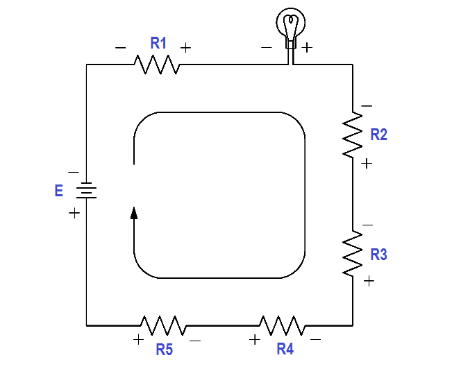
What Is Polarity In A Circuit At Jason Rocha Blog
Advanced Techniques and Considerations
6. Using an Oscilloscope
While a multimeter is great for measuring DC voltages and polarity, an oscilloscope can provide more detailed information about AC signals and waveforms. An oscilloscope displays a graph of voltage versus time, allowing you to visualize the shape of the signal and identify any anomalies. This can be useful for troubleshooting polarity issues in more complex circuits.
For example, if you're working with an AC circuit that uses a diode to rectify the signal, you can use an oscilloscope to visualize the input and output waveforms of the diode. If the diode is connected correctly, the output waveform should only have positive voltage. If the diode is connected backwards, the output waveform will have negative voltage.
An oscilloscope can also be used to measure the phase relationship between two signals. This can be helpful for troubleshooting polarity issues in circuits that use transformers or other phase-sensitive components. To use an oscilloscope for polarity testing, connect the probe to the point you want to measure and adjust the time and voltage scales to display the signal clearly.
Remember that an oscilloscope is a more advanced tool than a multimeter, so it's important to have a good understanding of how it works before using it for troubleshooting polarity issues. There are plenty of online resources and tutorials that can help you learn how to use an oscilloscope effectively.

FAQ
7. Q
A: Connecting a battery backwards can cause a short circuit, which can damage the battery and the device it's powering. In some cases, it can even lead to a fire or explosion. So, please, be careful!
8. Q
A: An LED damaged by reverse polarity might not show visible signs of damage, but it simply won't light up even when connected correctly afterward. Sometimes, it may have a slightly darkened or discolored appearance, but often the failure is internal.
9. Q
A: Generally, polarity isn't a concern with standard AC power outlets because the current alternates direction. However, polarity matters within devices that convert AC to DC, as well as in circuits containing polarized components like diodes and capacitors. Inside the device is where you need to worry about things.
